 FERMA-MOBILE
 Microclimate controllers
 Poultry weighing scales
 Silo scales
 Feed and water dispensing
 Lighting
 Alarms
 Extension modules
 Sensors
 Accessories
 Software
 Warranty terms
 Download
BITERMO-2S-485-LCD controller
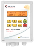
BITERMO-2S-485-LCD is a microclimate controller that controls work of fans and heaters depending on temperature and time (function of periodical ventilation). It has got four built-in control sections: each of them can work as ventilating or heating. All sections are of ‘ON/OFF’ type and they are used to direct supply of contactors coils (voltage outputs).
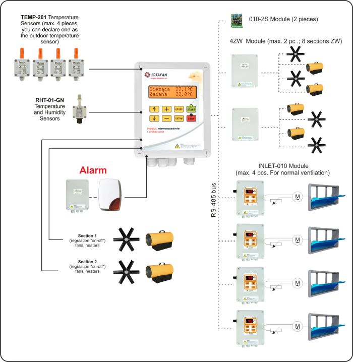
For extension of the system and its functionality the controller is equipped with a RS-485 digital bus for interoperation with extension modules of the JOTAFAN system. It enables additional connection of:
- up to 4 controllers of servomotors inlets (INLET-010),
- extension of the number of ‘ON/OFF’ sections- up to 8 independently programmed sections (Module 4ZW),
- RHT-01-GN temperature and humidity sensor,
- Module 010-2S to generate an analogue 0..10 V voltage for fluent control of servomotors.
The controller has got one relay alarm output and it indicates alarms e.g. when the set temperature thresholds are exceeded (temperature is too low or too high), in case of power supply failure, temperature measurement line damage etc.
Wiring diagram of the BITERMO-2S-485-LCD controller with sensors and modules control:

Characteristics:
- temperature measurement by means of a digital sensor TEMP-201, the sensor is included in the set,
- temperature and humidity measurement by means of a digital sensor RHT-01-GN,
- two built-in control sections ‘ON/OFF’ to direct control of electronic switches (each can work as ventilating or heating):
- a RS-485 module for communication with other JOTAFAN devices (extension modules of ‘ON/OFF’ section, controllers of servomotors inlets, etc.),
- relay alarm output (contacts NO, NC i COM), 24 V, 200 mA,
- large, easy to read LCD display with messages in Polish.
Functions:
- ventilation and heating control,
- change of the stage of section operation by means of one parameter: preset temperature,
- periodical ventilation: setting the cycles and levels of ventilation, bandwidth of ventilation (shortening the time of ventilation together with lowering below preset temperature in a building),
- alarm function i.a. in case of exceeding set thresholds of temperature (upper and lower threshold), failure of the control process, power supply failure, temperature measurement line damage, extension modules failure communication,
- the possibility of declaring the sensor of external temperature (i.a. in order to correct an alarm threshold or when temperature is too high).
| Supply voltage | 230 V, 50 Hz |
| Class of anti-electric shock protection | I |
| Kind of a control output of Section 1 | Electronic switch ~230 V, 50 Hz |
| Type of control of Section 1 | Two-position (ON/OFF) |
| Load current of an electronic switch of Section 1 | Imax: 0,5A (230 V, 50 Hz), Imin: 150 mA (about 35 W) |
| Type and kind of control outputs of Section 2 | Two-position: ON/OFF type, (relay contacts, NO, C) |
| Load current of relay contacts of Section 2 | Imax: 3 A (230 V, 50 Hz), Imin: 10 mA |
| The fuse in the power circuit | NOT INCLUDED-external circuit breaker of S type C-2 is required |
| The fuse in an output circuit of Section 1 | Ceramic 0,5A, 250V (IL≥1500 A) |
| The fuse in an output circuit of Section 2 | Ceramic 3,15A, 250V (IL≥1500 A) |
| A relay alarm output | Umax: 24 V DC, Imax: 200 mA, Rin: 8,2 Ω |
| Kind of an interface | RS-485 |
| Range of settings and temperature measurement | –5 ÷ +50 °C, resolution 0,1 °C |
| Range of temperature measurement | –40 ÷ +70 °C, resolution 0,1 °C |
| Range of temperature operation of sensor TEMP-201 | –25 ÷ +70 °C |
| Temperature of operation | 0 ÷ 40 °C |
| Ambient relative humidity | 10 ÷ 90 % (non-condensing) |
| Housing dimensions (height x width x thickness) | 220 x 160 x 93 mm |
| Device weight (without a temperature sensor ) | 0,7 kg |
| Type of a cooperative temperature sensor | TEMP-201 |


 Automatic controllers
 Print
Print