 FERMA-MOBILE
 Microclimate controllers
 Poultry weighing scales
 Silo scales
 Feed and water dispensing
 Lighting
 Alarms
 CA-GSM-1-LCD alarming unit
 ETC-3-AL controller
 ETC-2-AL controller
 ETC-1-AL thermometer
 ETC-1-AL-DLW thermometer
 ARITECH signaller
 Module P.S
 Antenna
 Extension modules
 Sensors
 Accessories
 Software
 Warranty terms
 Download
CA-GSM-1-LCD alarming unit
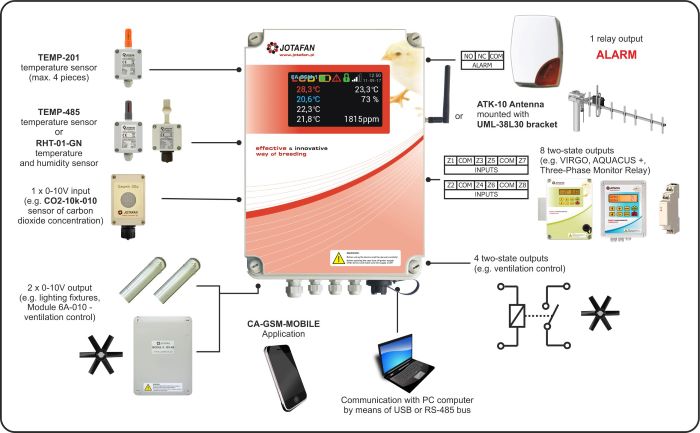
The CA-GSM-1-LCD alarming unit is designed for monitoring conditions in livestock buildings and informing the User by means of GSM communication, sending text messages (SMS) or calling (CLIP) to selected phone numbers in case of emergency situations (alarms). By means of GPRS it is possible to set remotely operation parameters of the alarming unit as well as download the history of operation. The alarming unit can also control the operation of acousto-optic signalling devices (e.g. AS510).
It is possible to connect to the alarming unit sensors of temperature, humidity and others, e.g. ammonia or CO2 and read their indications remotely (by SMS messages), check the status of interoperating devices and control them. The CA-GSM-1-LCD alarming unit interoperates with any SIM card, and as a result, it gives possibility to choose the best communication conditions and optimum costs.
Wiring Diagram CA-GSM-1-LCD with Sensors and Modules:

By means of the alarming unit it is also possible to control operation of other devices, using programmable outputs of ‘ON/OFF’ type and an analogue 0..10V output.
This alarming unit is equipped with a buffer power supply ~230 V with a battery that enables operation of the alarming unit without external power supply.
Battery charging and control system provide its long service time and send alarms about errors in its circuit (e.g. a worn-out battery).
Computer programme:
Full access to the CA-GSM-1-LCD alarming unit is possible by means of a computer programme that operates in Windows environment.
It is possible to connect to the alarming unit by means of the USB or RS-485 interface that are situated on the printed circuit board. After the initial configuration it is possible to communicate with the alarming unit via the Internet (GPRS connection).
The computer programme provides free configuration of the alarming unit including rich set of settings of inputs, outputs and external sensors as well as operation parameters, creating logical connections (between sources of alarms and telephones as well as control outputs), communication and self-check. Special attention should be drawn to the possibility of defining long SMS messages (160 characters) that may contain information about present status of the alarming unit and connected sensors (e.g. temperature and humidity values, level of GSM signal, status of inputs and outputs, etc.)
The programme also enables monitoring of current parameters and loading the history of operation from the memory of the alarming unit; arranging single readings in the chronological order.
Characteristics:
- the possibility of programming up to 8 phone numbers (and an additional service number), including different rights for each of them (basic, advanced, administrative),
- two independent passwords: for users and servicemen,
- free defining of inputs and outputs names included in SMS messages (up to 20 characters, without Polish letters),
- flexible configuration of SMS messages (up to 160 characters, without Polish letters) with the possibility of sending current parameters such as temperature, humidity, inputs and outputs status, counters, etc. with value set automatically,
- alarm thresholds for temperature, humidity and the input of analogue 0..10V signal set independently,
- a programmable, automatic test of communication,
- the possibility of getting information about the balance of an account on a pre-paid card and setting a reminder about expiring the term of its validity,
- self-check – check of supply parameters, GSM modem status, test of the quality of a battery, etc.,
- optical signalling of the alarming unit status: power supply, communication and signal level,
- memory of up to 8000 last events (together with date and time),
- the possibility of software update (without the need of disassembly of the alarming unit), also via the Internet.
Equipment of the alarming unit:
- modem GSM 900/1800 MHz that enables work in any subscription or pre-paid network
- 8 two-state inputs (configuration: 4- NO/NC/EOL/2EOL, 4 – NO/NC),
- 4 two-state outputs (one PNP high-current electronically protected 1A, the others of OC, NPN type 100Ma),
- one relay output (24 V, 200 mA, NO, NC, C contacts),
- one 0..10V input,
- two 0..10V outputs (5 mA),
- a bus for digital temperature sensors of JOTAFAN of TEMP-201 type (the possibility of connection up to 4 sensors),
- RS-485 bus for external devices, e.g. the RHT-01 sensor, extension modules,
- RS-485 bus for master controllers that control the operation of the alarming unit, e.g. a PC computer,
- USB interface for programming and diagnostics of the alarming unit,
- a buffer power supply with control of operation parameters, interoperating with maintenance-free 12V lead-acid battery, built-in battery with capacity of 2,3Ah,
- hermetic plastic housing of IP56,
- a control lamp on the front panel (signalling the presence of supply voltage, signal level, standby mode and an alarm),
- built-in anti-disturbance filters and surge protectors,
- FME socket for connecting an internal antenna or multi-element external antenna (in case of low level of signal in the building).
| Supply voltage | 230 V, 50 Hz (or from external battery: 12V, 2,3 Ah) |
| Power consumption | max. 40 VA ( 230 V, 50 Hz) |
| Class of anti-electric shock protection | I |
| Battery | lead-acid, maintenance-free 12 V, 2,3Ah |
| Power consumption from the battery | (standby mode, without peripheral devices) about 40mA |
| Maximum total load current of the unit’s power supply (terminals: „+12V”, „OUT1”) | 1,2 A |
| Type of an output 1 (OUT1) | PNP (voltage, ON/OFF +12 V) |
| Type of outputs 2, 3 ,4 (OUT2, OUT3, OUT4) | NPN, OC (Umax = 24 V DC) |
| Type of an ALARM output (OUT5) | relay, voltage-free NO, NC, C |
| Type of OUT 0..10V outputs (A1, A2) | voltage 0..10 V signal (Imax = 5 mA/output) |
| Type of IN 0..10 input | for a voltage signal 0..10 V (Rin = 42 kΩ) |
| Type of two-state inputs Z1, Z2, Z3, Z4 | NO/NC/EOL/2EOL (relative to COM terminal, polarised do +3V by R = 2,2 kΩ) |
| Type of two-state inputs Z5, Z6, Z7, Z8 | NO/NC (relative to COM terminal, polarised +12 V by R = 4,7 kΩ) |
| Kind of an interface ‘BUS’ and ‘MASTER’ | RS-485 |
| Range of settings and temperature measurement | –25 ÷ +60 °C |
| Resolution of a setting and temperature measurement | 0,1 °C |
| Type of a cooperative sensor of temperature | TEMP-201 (max. 4 pieces.) |
| Type of cooperative sensor of temperature and humidity | RHT-01-GN (max. 1 piece) |
| Kind of GSM communication | GSM/GPRS, 850/900/1800/1900 MHz |
| Type of antenna’s GSM socket | FME |
| Temperature of operation | 5 ÷ 40 °C |
| Ambient relative humidity | 10 ÷ 90 % (non-condensing) |
| Ingress protection class | IP55 |
| Housing dimensions of the WGJ-8 panel (length x width x height together with an antenna socket) | 340 × 242 × 129 mm |
| Device weight (without a temperature sensor) | 3,9 kg |


 Print
Print