 FERMA-MOBILE
 Microclimate controllers
 Poultry weighing scales
 Silo scales
 Feed and water dispensing
 Lighting
 Alarms
 Extension modules
 Sensors
 Accessories
 Software
 Warranty terms
 Download
TERMISTAT–6–4S–485–LCD+ controller
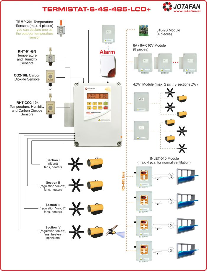
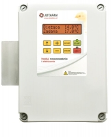
TERMISTAT-6-4S-485-LCD+ is a microclimate controller that controls work of fans and heaters depending on temperature and time (function of periodical ventilation). It has got four built-in control sections: each of them can work as ventilating or heating. One is electronic with fluent power control of single-phase fans or infrared illuminators with current up to 6A. The other three sections are of ON/OFF type ( voltage outputs )
Optionally Section 3 can be configured to work as tunnel-ventilation and Section 4 - to control the cooling system by fogging with humidity control.
For extension of the system and its functionality the controller is equipped with a RS-485 digital bus for interoperation with extension modules of the JOTAFAN system.
It enables additional connection of:
- up to 8 extension modules of fluent section (MODULE 6A, MODULE 6A-010),
- up to 4 controllers of servomotor inlets (INLET-010),
- extension of the number of ‘ON/OFF’ sections- up to 8 independently programmed sections (Module 4ZW ),
- RHT-01-GN temperature and humidity sensor, CO2-10K carbon dioxide sensor or RHT-CO2-10K integrated sensor,
- Module 010-2S to generate an analogue 0..10 V voltage for fluent control of servomotors inlets.
The controller has got one relay alarm output and it indicates alarms e.g. when the set temperature thresholds are exceeded (temperature is too low or too high), in case of power supply failure, temperature measurement line damage etc.
Wiring diagram of the TERMISTAT-6-4S-485-LCD controller with sensors and modules control:

Characteristics:
- temperature measurement is made by means of digital sensors, the possibility of connection of up to 4 sensors TEMP-201, one sensor is included in the set,
- temperature and ambient relative humidity measurement (RHT-01-GN),
- carbon dioxide concentration measurement (CO2) by means of CO2-10K sensor, automatic ventilation starting, when the carbon dioxide concentration is too high - alarm
- four built-in control sections (each can work as ventilating or heating)
-Section 1, ‘fluent’ – it enables the multistage (100 stages) control of single-phase fans or infrared illuminators with current up to 6A
-Section 2,3,4 ‘ON/OFF’ type- with a voltage output to direct control an electronic switch
- tunnel-ventilation,
- a RS-485 module for communication with other JOTAFAN devices (extension modules of ‘fluent’ section, controllers of servomotors inlets, etc.),
- relay alarm output (NO, NC and COM contacts), 24V, 200mA,
- large, easy to read display LCD with messages in Polish.
Functions:
- choice of the mode of outputs operation (ventilation/heating),
- change of the stage of section operation and thermal alarms by means of one parameter: preset temperature,
- defining the minimum and maximum control of the fluent section,
- a 'forbidden range' – elimination of the part of the fluent section control range that is energy-intensive and adverse for work of fans,
- periodical ventilation: setting the cycles and levels of ventilation, bandwidth of ventilation (shortening the time of ventilation together with lowering below preset temperature in the building),
- alarm function i.a. when temperature thresholds are exceeded (temperature is too low or too high), when the control process has been stopped, in case of power supply failure, temperature measurement line damage etc.,
- diversity of characteristics of inlets operation in terms of the fluent section in order to generate differential pressure,
- the possibility of declaring the sensor of outside temperature (i.a. in order to correct an alarm threshold or when temperature is too high).
| Supply voltage | 230 V, 50 Hz |
| Class of anti-electric shock protection | I |
| Type of control of Section 1 | phase |
| Maximum continuous load current of Section 1 | 6 A |
| The minimum continuous load current of Section 1 | 150 mA (about 35 W) |
| The fuse in the power circuit of Section 1 | an external circuit breaker of S type B-6 is required ( B, In=6 A) |
| Type of control of Section 2, 3 and 4 | Two-position (ON/OFF) |
| Types of control outputs of Section 2, 3 and 4 | electronic switch ~230V, 50Hz |
| Load current of electronic switches of Section 2, 3 and 4 | Imax: 0,5 A (230 V, 50 Hz), Imin: 150 mA (about 35 W) |
| The fuse in the power circuit of Section 2, 3, and 4 | Ceramic 0,5A, 250V (IL≥1500A) |
| Relay alarm output | Umax: 24 V DC, Imax: 200 mA, Rin: 8,2 Ω |
| Type of serial communication input | RS-485 |
| Range of setting temperature | –5 ÷ +50 °C, resolution 0,1 °C |
| Range of temperature measurement | –40 ÷ +70 °C, resolution 0,1 °C |
| Range of temperature operation of sensor TEMP-201 | –25 ÷ +70 °C |
| Resolution of a relative humidity setting | 1 % |
| Resolution of a CO2 concentration setting | 50 ppm |
| Temperature in immediate vicinity of the controller | 0 ÷ 40 °C |
| Ambient relative humidity | 10 ÷ 90 % (non-condensing) |
| Ingress protection class | IP55 |
| Housing dimensions (height x width x thickness together with a radiator) | 315 x 285 x 130 mm |
| Device weight (without a temperature sensor) | 2,4 kg |
| Type of a cooperative temperature sensor | TEMP-201 |


 Automatic controllers
 Print
Print