 FERMA-MOBILE
 Microclimate controllers
 Poultry weighing scales
 Silo scales
 Feed and water dispensing
 Lighting
 Alarms
 Extension modules
 Sensors
 Accessories
 Software
 Warranty terms
 Download
The VIRGO controller
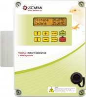
The VIRGO controller is an electronic device used to control ventilation (chimney, cross-flow, tunnel) as well as heating and spraying on the basis of temperature, humidity and carbon dioxide concentration.
This controller is a versatile device because it is equally easy to carry out the extended multi-parameter system as well as the basic system- one or two-section with control only as function of temperature. In both cases: the extended controller or the basic one, their operation is easy and friendly.
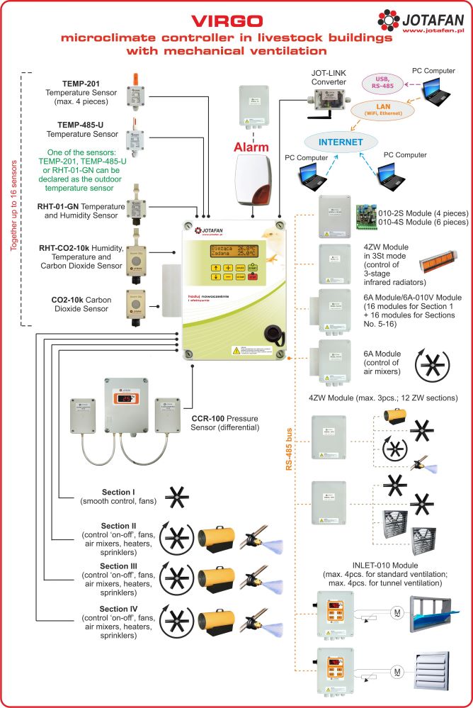
The full equipment of the VIRGO controller includes:
- 16 sensors (temperature, humidity and carbon dioxide concentration,
- 16 control sections (4 built-in, 12 external; standard and tunnel ventilation as well as heating and spraying),
- 4 inlets sections (for standard ventilation as function of its efficiency or regardless of section work only as function of temperature),
- 4 tunnel inlets sections to cooperate with sections of tunnel ventilation,
- 1 pressure sensor (differential).
Wiring diagram of the VIRGO controller with sensors and modules control:

The VIRGO controller has the following functions:
- ventilation based on temperature, humidity and carbon dioxide concentration,
- preset temperature adjusted manually or automatic change according to the curve,
- night temperature (it improves the welfare and efficiency of breeding),
- periodical ventilation (it also has the function of minimum ventilation),
- dehumidification and humidification,
- multi-zone heating,
- multi-zone spraying,
- alarms,
- operation history recorded with date and time (alarms and cyclic record of parameters),
- connection to the PC computer and remote monitoring over many VIRGO controllers - also via the Internet,
- software designed for communication, data collection and their visualization in the shape of charts and tables.
The VIRGO controller records its operations history: values of measured parameters, alarms. It enables the continuous control of breeding and its verification after finishing the breeding process. After reading the operation history on a PC computer it can be presented in the shape of charts and tables. A built-in interface gives possibility to connect many VIRGO controllers to the network and their control by means of a PC computer - the system can also be set up for remote monitoring via the Internet. In order to interoperate with a computer the controller requires use of a USB<=>RS-485 converter.
During its work the controller responds to some inaccurate situations. In order to inform about them it has been equipped with a relay alarm output. An alarm is activated i.a. when the power supply of the controlling device is turned off, when a defect in temperature measurement is detected, programmed limits of temperature values are exceeded, when the process of control is stopped or when irregularities in controller’s operation are detected (e.g. a failure in memory settings). Alarm messages are also visible on the controller’s display.
The procedure of configuration of a climate control system by means of the VIRGO controller can be as follows:
- The type and number of temperature, humidity and carbon dioxide concentration sensors should be specified- in total up to 16 sensors. The function of the external temperature can be set for one of the temperature sensors.
- The type and number of control sections should be specified- in total up to 16 sections (4 built-in and 12 external) - each section (except the first fluent section that can only be the standard ventilation) can work as: standard ventilation, tunnel ventilation, heating or spraying (only ON/OFF sections, cooling by spraying or humidification when humidity is too low). In case of ventilation sections their number should also be specified.
- Sections should be connected to selected sensors in order to obtain the optimum process of climate control. Thanks to this function a henhouse can be divided into zones or heaters can start their work independently on the basis of temperature measurement in their immediate vicinity.
- If there are inlets - one should set their dependence on present section efficiency (multi-point curves) and kind ('standard' inlets and tunnel inlets). It is possible to vary the inlets (up to 4 independent) and connect them to the work of relevant sections. It is also possible to adjust inlets independently - for work as function of temperature. A novelty is taking into account the time of inlets movement during the ventilation process. It enables to keep the expected differential pressure and it prevents falling cold air directly on animals near the wall where inlets are situated.
- One should set breeding parameters including the hour of the end of the day of breeding, temperature curve and the like.
- One should adjust possible temperature reduction during illumination break (welfare improvement)
- Alarm thresholds should be set, e.g. dependent on temperature.
| Supply voltage | 230 V, 50 Hz |
| Fire protection class | I |
| Type and kind of control of Section 1 | phase |
| The maximum continuous load current of Section 1 | 6 A |
| The minimum load current of Section 1 | 150 mA (about 35 W) |
| The fuse in the power circuit of Section 1 | External circuit breaker of S type B-6 (type B, In=6A) |
| Type of control of Section 2, 3 and 4 | two-position (ON/OFF type) |
| Types of control outputs of Section 2, 3 and 4 | electronic switch ~230V, 50Hz |
| Load current of electronic switches of Section 2, 3 and 4 | Imax: 0,5A (230V, 50Hz), Imin: 150mA (about 35W) |
| The fuse in the power circuit of Section 2, 3, and 4 | Ceramic 0,5A, 250V (IL≥1500A) |
| Relay alarm output | Umax: 24V DC, Imax: 200mA, R: 8,2Ω |
| Type of serial communication input | RS-485 |
| Range of setting temperature | –5 ÷ +50°C, resolution 0,1°C |
| Range of temperature measurement | –25 ÷ +69,9 °C, resolution 0,1 °C |
| Range of temperature operation of sensor TEMP-201 | –25 ÷ +70 °C |
| Resolution of a relative humidity setting | 1% |
| Resolution of a CO2 concentration setting | 50ppm |
| Temperature in immediate vicinity of the controller | 0 ÷ 40°C |
| Ambient relative humidity | 10 ÷ 90% (non-condensing) |
| Ingress protection class | IP55 |
| Housing dimensions (height x widtht x thickness together with a radiator) | 315 x 285 x 130mm |
| Device weight (without a temperature sensor) | 2,4kg |
| Type of a cooperative temperature sensor | TEMP-201, TEMP-485-U, RHT-01-GN, CO2-10K, RHT-CO2-10K |


 Automatic controllers
 Print
Print